Database structure diagrams
You can view a database structure in the standard ERD (Entity Relation Diagram) form. ER diagrams are available for all tables and schemas (databases.md).
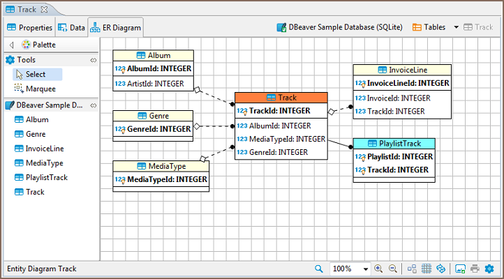
The ER diagram for a table shows the table itself and its relations with other tables inside the schema. To view the ER diagram for a table or view, double-click the table or view in the Database Navigator and then, in the Database Object Editor, switch to the ER Diagram tab:
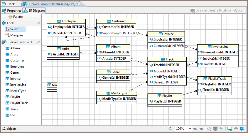
To view the ER diagram for a full database schema, double-click the schema name in the Database Navigator or the previous node in the path (usually - Tables):

NOTE: Table and schema diagrams are read-only. You can rearrange the layout, drag-n-drop elements inside a diagram but you cannot save the changes state or delete/add anything. This is because the diagrams represent the actual state of databases.
Relationship Notation
Lines representing the relationship between tables can look different depending on the nature of the relationship. Please note that any line can have only one beginning and one end. Even for one-to-many and other relationships that imply otherwise. In those situations you will just see more than one line.
| Notation | Description |
|---|---|
 |
The solid line means that the foreign key column is also a primary key in a referencing table |
 |
The dashed line means that the foreign key column is not a primary key in a referencing table |
 |
If the relationship between two tables is other than one-to-one, you will see multiple lines that all start at the same one point and all merge at the end point. |
 |
The black dot represents the beginning of the line and is attached to a table that has a foreign key referencing another table |
 |
The white rectangle represents the end of the line and is attached to a referenced table. It only appears at the end of the dashed line |